| Author |
Message |
|
Joolz
Firing on two.
Joined: January 5th, 2009, 5:48 am
Posts: 1687
Location: Haven't a clue

|
 Re: Joolz's Red One OK, the solution to the issues mentioned above, wheel spacers. Now I know other people might have drawn them on a CAD program, and then emailed it to somewhere that could CNC them, but that's not how I roll. I've got the time and to me this is easier. They were cut from a sheet of 6mm ali, the holes were originally drilled 11.5mm and then filed to make sure they were a perfect fit, and then for the final truing up they were mounted on a spare hub in the lathe. 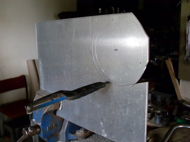 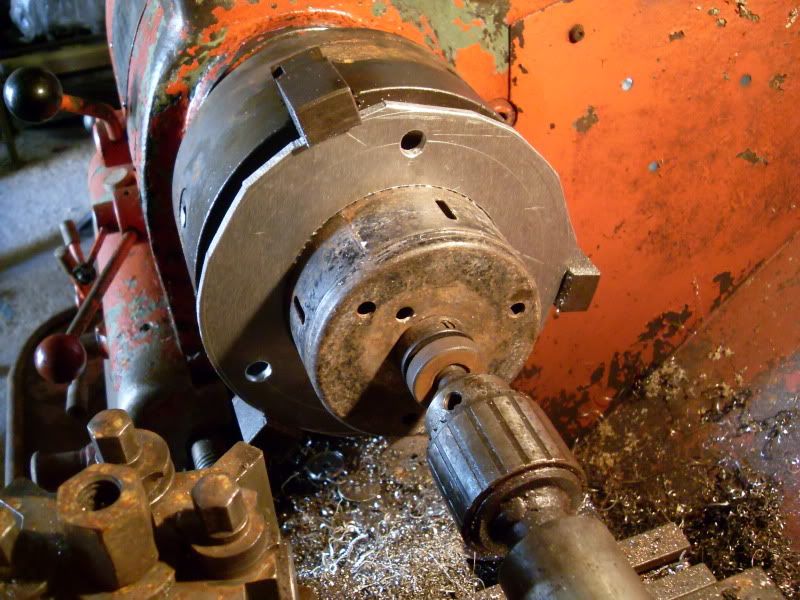 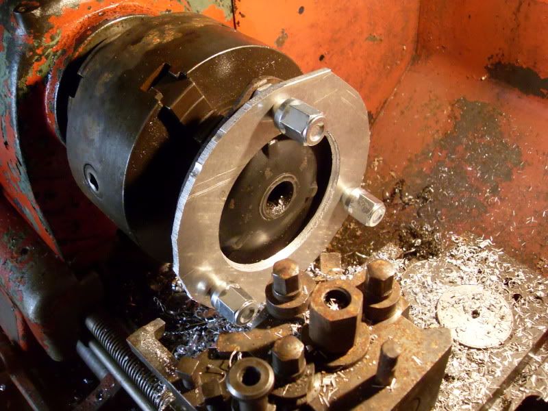 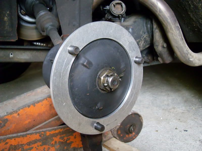 The wheel nuts now only go on 8 turns, obviously I'm hoping this is enough, but educated comments would be welcome.
_________________

|
| April 5th, 2011, 11:33 pm |

|
|
|
Russell
Firing on two.
Joined: November 29th, 2008, 10:05 pm
Posts: 9259
Location: West Sussex, U.K.
|
Re: Joolz's Red One Nice work, as usual. How many threads do the original nuts turn with original wheels?
_________________
samfieldhouse wrote: What I like about I2F is that there is no pretence of democracy.
|
| April 6th, 2011, 7:51 am |
|
|
|
Tim2cv
gym bunny
Joined: December 8th, 2008, 4:08 pm
Posts: 806
Location: Burton-upon-Trent
|
Re: Joolz's Red One Brilliant work mate... so jealous, would love a lathe, mill drill machine.... CNC machine!!!  Fingers crossed them spacers pull the rims out far enough. Once you can make GS/A to 2cv shafts adapters you're on to a winner... I've got just the test vehicle too!
_________________

1299cc FTW
|
| April 6th, 2011, 8:31 pm |

|
|
|
Joolz
Firing on two.
Joined: January 5th, 2009, 5:48 am
Posts: 1687
Location: Haven't a clue
|
Re: Joolz's Red One I've done something I should have done ages ago, and put a fire extinguisher in the car. There's just enough space to fit it at the side of the drivers seat, and while I could have cable tied it to the seat frame, you know me better than that. In case anyone wondered how the Hyundai seats mount, here's a pic of the frame. 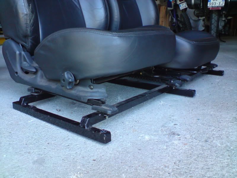 The easiest way to get them out of the car is both together on the frame, but they're bloody heavy and awkward, and I ended this job by touching up the paint on the sills. I cut a couple of pieces of 25 x 6mm flat bar and drilled and tapped them M5, then welded them on the frame, a bit of paint and it almost looked professional. 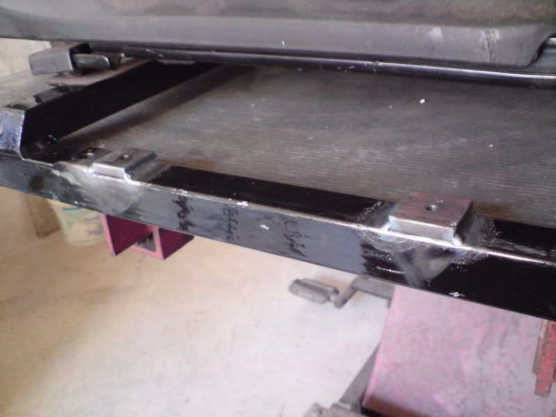  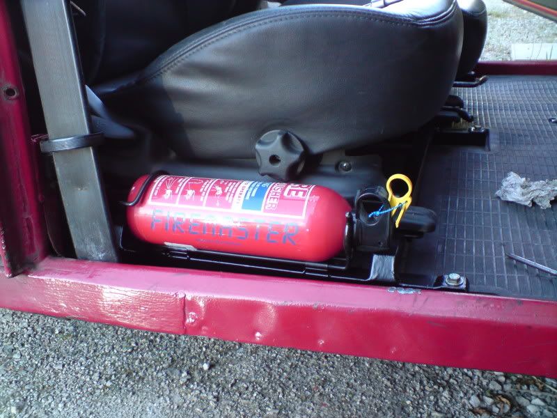 Considering the amount I've modified the wiring, and the fact it's got a diy high pressure fuel system, this is probably a good investment, but then most 2cv fires seem to be caused by the heater tubes, and I haven't got any of those. To make enough room I had to swap the seat belt around and move the recoil part to behind the B-pillar, but it seems to work equally well either way.
_________________
|
| April 18th, 2011, 1:40 am |
|
|
|
Joolz
Firing on two.
Joined: January 5th, 2009, 5:48 am
Posts: 1687
Location: Haven't a clue
|
Re: Joolz's Red One I've been thinking about fitting megasquirt to my car for some time now, for the uninitiated it's a diy engine management system, and I was intending to start over the winter while it was too cold to do much else. So much for that plan, it was March by the time I ordered the kit, and I finally got my hands on it last week. Electronics aren't my thing, so this is a bit scary. On a good day I think how hard can it be if I put my mind to it, and other days it's WTF have I got myself into. The bits I ordered were little more than an ECU kit and a couple of cables and cost about £250, plus customs wanted another £60 to let it into the country as it comes from the U.S. As it comes out of the box the kit looks pretty much like this, thankfully the instructions which are all online are quite comprehensive. 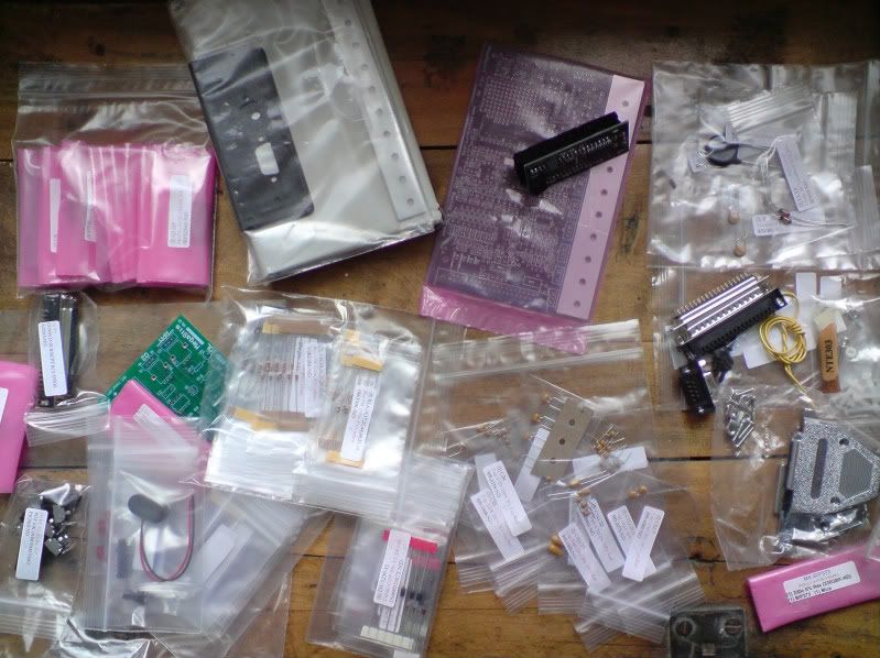 The first thing to do is to assemble the stimulator, not actually a marital aid, but a small device that helps to test and set up the ECU by mimicking the signals it would expect to see from the engine. It went together easily enough and boosted my confidence that this whole idea might just be doable. 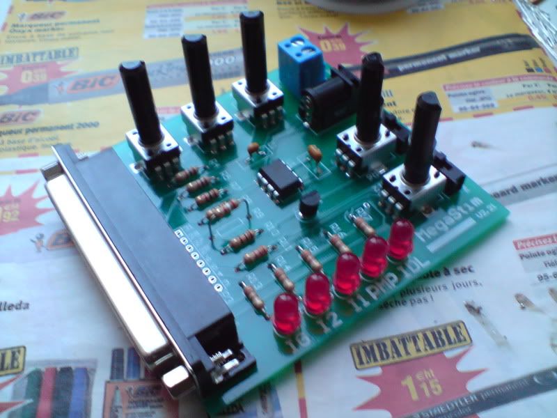 I've now started on the main ECU board which is much more complicated and fiddly. I've completed stage 1 of the construction which is the power supply and that seems to be working fine. The instructions recommend that you work in stages and test the different sections as you go, in the event of you making a mistake it would make fault finding much easier. Most of the instructions are simple enough, and just need following carefully, but I just got to the first optional bits, so in order to decide if I want a jumper wire from JS10 to IGN, or IGBTIN, with IGBTOUT linked to IGN, I'll have to try and work out WTF that all means. For now I might just gloss over it, and carry on with the slightly simpler task of just soldering bits where they tell you. The actual soldering is surprisingly easy apart from some of the contacts being bloody tiny. 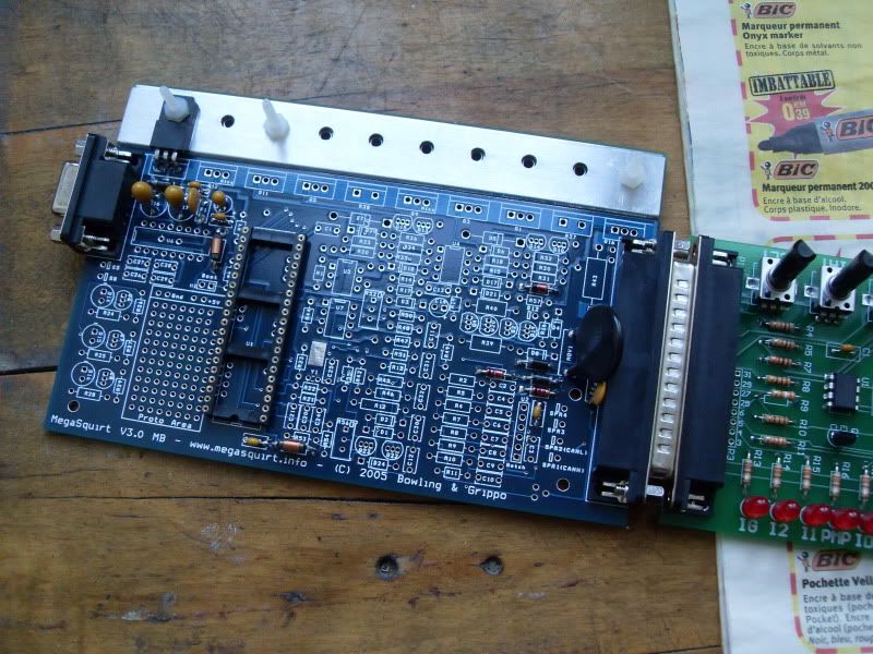
_________________
Last edited by Joolz on May 31st, 2011, 10:27 pm, edited 1 time in total.
|
| May 13th, 2011, 1:13 am |
|
|
|
Harley
Firing on two.
Joined: May 3rd, 2009, 11:40 am
Posts: 816
Location: Melbourne, Australia.
|
Re: Joolz's Red One The Testicles are large with this one..! Bloody good on you for D.I.Y.ing it, it makes it the cheapest most tuneable ECU on the market. The knowledge base and information on the net is indeed vast, daunting at times, I found that there is in fact to much information on the net and the best approach is to just do/try it and see what happens. Although I did buy the Stim and ECU already assembled as my testicles aren't that large  But i will never forget when the engine started the first time, fire extinguisher at the ready! I was so fulfilling! Which processor are you running, MS II or MS III? I will be interested how you do the twin spark ignition as that is where i am at, but i keep procrastinating because i need to upgrade from MS I to either II or III OR buy a KDFI unit and use the MS I on my DS.... Joolz = LEGEND! Harley
_________________
samfieldhouse wrote: It is M9 for the shocks yes, the rest I'll check when next i'm underneath her. Ironically, this will be valentines day.
|
| May 14th, 2011, 4:12 am |
|
|
|
lpgo
Firing on 1-2 Spark
Joined: November 8th, 2009, 5:42 pm
Posts: 2847
Location: NL
|
Re: Joolz's Red One Wish you a steady hand Joolz!!!
But surely you can do this......
This is almost like getting a child/getting maried (see your'e car first time running on a selfmade ingition/injection) well you know what I mean.
I'm making my own ignition from scratch now see my topic (1-2-spark), and after learning how to programm a Ic and having the right electronics is is rather simple to spark a 2cv.........
p.s. Read the manual(s) on the web over and over and over and over, and when you read again suddenly all becomes clear, jumper ingn. on JS10, IGTB in and out.
My advice run on MS2extra and configure your board to this
try to go right away for 2 tach signals (crank 36/1 wheel with VR sensor and
cam with hall sensor so you can do sequential ignition/injection).........
Keep the good stuff coming up!!!!
_________________
Russell wrote: Hi Geo,
you've been one of the sites biggest attractions in recent years.
Russ
|
| May 14th, 2011, 9:21 am |
|
|
|
Joolz
Firing on two.
Joined: January 5th, 2009, 5:48 am
Posts: 1687
Location: Haven't a clue
|
Re: Joolz's Red One I mostly went with the kit option because it was cheapest, but also because buying a pre-built one would be accepting that I couldn't do it myself, and I like to imagine I can do most stuff if I set my mind to it, and that stuff I don't know is just stuff I haven't learnt yet. Computers are one of those things that I haven't managed to get my head around yet, mostly I think it's a mental block because they just don't interest me, my understanding of them pretty much begins and ends with switching one on and opening a web browser. I did try reading as much as I could before I started, but without having physical stuff in front of me the information just doesn't stick, plus the manuals are full of anachronisms and unfamiliar terminology (geek speak), so by the time you've looked up what all the words mean, you've lost the gist of what they're talking about. That's why I thought I'd just get started and work it out as I go. The soldering's not difficult, although good light and steady hands certainly help. Yesterday I got to the second test stage which involved downloading something called 'Hyper terminal' onto the laptop and then connecting it to the the megasquirt with a DB-9 cable, then with two of the pins in the processor socket shorted together, typing characters on the keyboard made them appear in the 'Hyper terminal' window. Now typing on a laptop and having it appear on the screen doesn't sound like a big deal, but apparently that shows it's working. And with the processor socket pins not shorted nothing appeared on the screen so I guess it's doing something, I just don't really understand what. Today I got to the next testing stage, (step 40 here) and so far it's got me beat, I'm sure it's something a lot of computer literate people could do, downloading and installing some program/code, I tried following it word for word, but it assumes some background knowledge that I just don't have. I'll have another look tomorrow, but I might have to try and find an I.T. friend.
_________________
|
| May 14th, 2011, 11:46 pm |
|
|
|
Joolz
Firing on two.
Joined: January 5th, 2009, 5:48 am
Posts: 1687
Location: Haven't a clue
|
Re: Joolz's Red One @Harley, I went for an MS-II on a V3.0 board because I think it was the minimum that I needed, I can't remember if I read about what extra stuff an MS-III can do, it's quite new isn't it, but any extra complications wouldn't have been welcomed. Although my engine has twin plugs, it's been running on just one for the last year, turned out there was a relay missing. In my defence I haven't got a wiring diagram for the twin spark model, and while it was running ok I hadn't looked into it too hard. Running it on all the plugs doesn't seem to have made a noticeable difference so if I can't fire all the plugs I won't worry too much. However I'm hoping that it won't be too difficult, and that I can run a second coil driver in parallel with the one standard one, I ordered an extra bip373 with the kit. I know that you were looking at a feature to do this, I did read about it too, but I can't remember what it was called or even if it was hardware or code. Like I say, stuff doesn't stick in my head easily, except I seem to remember it being useful for V-engines. However I'm hoping that it can be done much more simply with a flat twin engine, because all four plugs fire at the same time. @lpgo, I read your 1-2-spark, now that's clever, I'm just following instructions. I heard that sequential injection can give better economy at low throttle openings, but there is no easy place to put a cam sensor on my engine, I also thought about putting a VR sensor on the flywheel, but for now I will just use the hall sensor on the front of the crank, because it is there already and works fine for the standard system.
_________________
|
| May 15th, 2011, 12:01 am |
|
|
|
Joolz
Firing on two.
Joined: January 5th, 2009, 5:48 am
Posts: 1687
Location: Haven't a clue
|
Re: Joolz's Red One Just a quick update in case anyone was wondering how it was going, and because I'm quite pleased at having made a breakthrough. The last 2 weeks have involved only about an hour of soldering, but many hours of head scratching. But finally the code is loaded onto the processor and the tuning software on the laptop is talking to it. The last week has been spent wondering why the tuning software said there was no code loaded, and a PortCheck program couldn't make any connection. It turned out to be as simple as having to have the power to the board switched on before plugging in the serial cable, just a quirk apparently, but very frustrating until I found out. The good news is that so far the board seems to be all working as it should, and twiddling the pots on the stimulator result in the needles moving on the on screen dials. 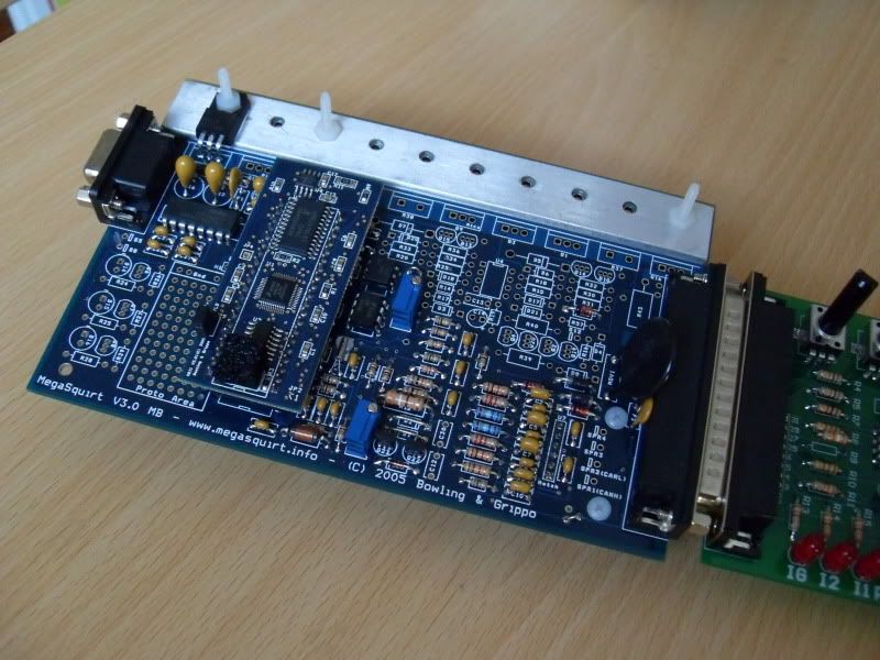 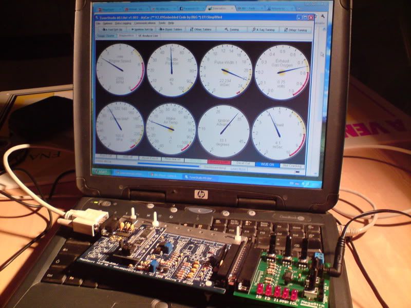
_________________
|
| May 31st, 2011, 11:15 pm |
|
|
Who is online |
Users browsing this forum: No registered users and 9 guests |
|
You cannot post new topics in this forum
You cannot reply to topics in this forum
You cannot edit your posts in this forum
You cannot delete your posts in this forum
You cannot post attachments in this forum
|
|